Fixing a rare Intel Xeon Phi motherboard which forgot how to network
I have a four node Intel Xeon Phi server. I got this roughly four years ago during Covid after reading about Brandon Falk's vectorized emulation endeavors. Brandon also streamed a lot of his development work on YouTube and I thought to myself: "Hey, I can implement this too" and so I did together with a friend, but that's a topic for another day.
Below you can see the case with one of the nodes that can be plugged into the back. I have four Intel Xeon Phi 7230 nodes, two of them with 48GiB of memory for vectorized emulation experiments. The node's product designation is HNS7200AP which contain an S7200AP motherboard that supports the Xeon Phi x200 Knights Landing CPUs. There are also refreshed variants called HNS7200APR/S7200APR with a slightly modified motherboard that has a different CPU core voltage regulator for the Xeon Phi x205 Knights Mill CPUs. I have two of these as well, but that's also a topic of another blog post.
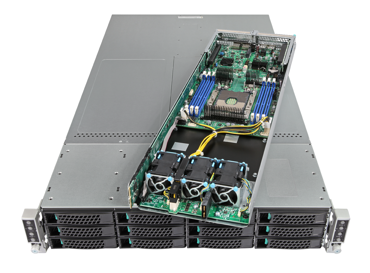
The four-node Xeon Phi chassis with one of the four nodes sitting on top
The whole chassis is sitting in a datacenter. This is mostly because at the time I got it, I was living in a rented apartment without a real cellar or other place to put an obnoxiously loud server. Every time we write software or play around we would connect to the IPMI running on the BMC and turn on the node, do our stuff and turn it off again, because power costs money, even in a datacenter. Only two of the nodes have actual memory DIMMs and an mSATA SSD to boot from installed. The other two are functional, but only with the 16GiB on-CPU-MCDRAM and by booting from the network. We very creatively call them phi1 to phi4 and we mostly used phi4 for our experiments.
If I remember correctly, we had a power outage once in the data center. Anyway, something happened and after that phi4's BMC wouldn't acquire a DHCP lease anymore and the managed switch it was connected to showed the link as down. We power cycled everything and the state remained. Weird. Maybe something on the motherboard blew up? I didn't have the time to drive by the DC and check it out, so we just used phi3 from this time on, because it was equally equipped as the now dead phi4.
Until earlier this week... I drove by, checked out the node and turned it on manually. It booted. But the BMC was still unreachable. I shut it down, pulled out the node a bit from the chassis and slid it back in, just for good measure. Same thing. And then I decided to pull it out, take it with me and just check it out at home.
🔗The Xeon Phi
I have been talking about the Xeon Phi in the first paragraph, but what even is that thing? If you know what this is or just don't care, you can skip ahead.
It's a pretty weird CPU built by Intel for heavy number crunching in supercomputer applications. It all started with Project Larrabee which was an attempt by Intel to build a GPU. They took what they already had, which was a P54C Pentium 1 x86 core, and just slapped a shitton of them next to each other. The advantage of such an old core is that it is small by modern standards, so a lot would fit on a die. But it's also a relatively slow in-order core.
A GPU needs to run a lot of code to process data in its programmable shader units. The input data to each of the units is different, but the executed code is exactly the same. Intel's idea was to use a lot of x86 cores to perform these tasks. The first prototype of such an architecture was called Knights Ferry and came in the form of a PCIe card with 32 of these in-order x86 cores and 2 GiB of memory. As far as I know, these cards were distributed to research institutes and universities.
Based on this first experience, Intel would design the first publicly available manycore chip: Knights Corner. They added 4-way Hyperthreading and a vector processing instruction set to the CPU cores which would later become known as AVX-512, but this version isn't binary compatible with it. This was supposed to be the base for their new GPU of which they even built actual Prototypes of. A few have been sold on the Internet, but nobody has the needed drivers and the graphics stack that goes with it. According to a blog post of an engineer who worked on this stuff at Intel, all of this existed and it actually rendered something and didn't even perform that bad.
However, Intel axed the whole GPU thing. They kept the weird manycore architecture they developed for this and announced the "Xeon Phi" accelerator cards with codename Knights Corner which essentially already was the hardware for the GPU they developed. They even still have texture sampling units on the die and just never used nor documented them. Knights Corner came again in the form of a PCIe add-in card. This is the first "Xeon Phi" chip which was available to the general public and not just a special prototype thing. I have one, but never really used it. They are ubiquitous and sold on eBay in huge numbers, but they are also kinda trash because they are so slow.
After that, Intel developed a new version called Knights Landing which now supports the actual AVX-512 instruction set and has CPU cores which support out-of-order and speculative execution. Instead of the old Pentium P54C cores, they switched to Intel Atom Airmont cores, hence all the newly supported modern CPU features that make things go more brrrrr. It again came in the form of PCIe accelerator cards, but also as standalone CPUs that could boot by themselves. This is what we are talking about here in the blog post. I also have an accelerator card, but they only saw the light of day for a very short time until Intel cancelled them altogether. I managed to find one years ago on eBay in Australia and haven't seen them again. Also a nice topic for another blog post, because it's essentially a whole PC including a chipset on a PCIe card together with a PCIe non-transparent bridge to, well bridge, the host PCIe bus with the bus on the CPU on the card.
The final and last version of the Xeon Phi was Knights Mill. These CPUs were a relatively minor iteration on Knights Landing which brought support for hardware virtualization, AVX-512 Fused-Multiply-Accumulation- and Deep-Learning-Instructions. They also came with a massively higher power consumption and TDP for which refreshed versions of the motherboard were required. They launched in December 2017 and shortly after they became available, Intel phased them out as well and the whole Xeon Phi product series was essentially dead including the already planned successors called Knights Hill and Knights Peak. The new shining star on Intel's GPU and accelerator sky was supposed to be Intel Xe from now on.
There is a lot more to explain about these things: The tiles that contain CPU cores, vector units and the first layers of cache, the interconnect between the tiles, the on-package 16GiB MCDRAM introduced with Knights Landing and much more. There are whole books out there about this thing.
In summary, the Xeon Phi is a CPU with a huge amount of slower cores. The single-thread performance is horrible for something labelled as a Xeon, but that's not the selling point of the Phis: It's the core count in conjunction with the AVX-512 support. If you have a problem that you can parallelize and vectorize, these things crushed everything (at least every other x86 machine...) when they came out. For a long time this also was the cheapest option if you wanted anything with AVX-512 support. Proper Xeons are expensive, on the consumer side Alder Lake supported it on the P-Cores, but Intel fused it off in later revisions. Nowadays you should just buy an AMD Zen 4 if you want to play with this. They support it out of the box and even more instructions than the Phi: Namely AVX512{VL,DQ,BW}.
Here are a few more sources for the elaborated reader:
- Chips and Cheese - Knight’s Landing: Atom with AVX-512
- Intel® Xeon Phi™ Coprocessor Architecture Overview
- Intel® Xeon Phi™ Coprocessor x200 Product Family
- Parallel Programming and Optimization with Intel Xeon Phi Coprocessors
- Intel Xeon Phi Processor High Performance Programming: Knights Landing Edition
- Intel Xeon Phi on Wikichip
🔗The motherboard
The motherboard of one of the nodes looks like a normal single-socket Xeon motherboard in a weird blade form-factor, but it is specifically made for the Xeon Phi x200 (the product name of Knights Landing). There are four (eight if you count the ones with the integrated OmniPath fabric) different variants of the CPUs with 64 to 72 cores and different clock speeds. They are all most likely the same die which get frequency-binned and broken cores are fused off to increase the production yield.
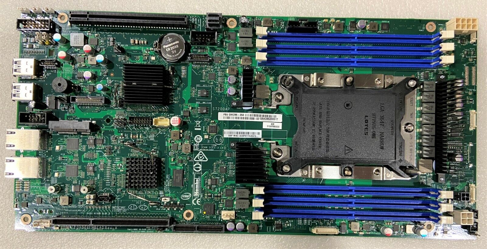
The top view of an Intel S7200AP motherboard
The board is a typical server board with the CPU socket on the right side. Around it various multi-phase voltage regulators for core voltages and DIMM-slots for DDR4 Registered ECC memory.
On the left side of the board are the chipset, an Emulex Pilot 3 BMC, two Intel i210 Gigabit Ethernet PHYs, multiple serial flashes for the UEFI, BMC firmware and ethernet PHY firmware and config as well as a shitton of support circuitry and voltage regulators.
The form factor is obviously weird and nothing like ATX. It is meant to be installed in one of these blades and shoved into a chassis which contains the power supplies, SATA/SAS/NVMe backplane and mundane things like a power/reset switch and a few LEDs. Now I only have one chassis which sits in a datacenter and I took just the node home with me. Now what? How do I power it?
🔗Booting the node without a chassis
While scrolling through the Technical Product Specification of the S7200AP, I found a nice top view of the board with all of the connectors nicely labeled.
Usually, when the board is installed in the node, a bridge board (I call it the "long boi") is plugged into the appropriate connector on the board and follows the top wall of the node chassis to the front where it is plugged into the backplane. It carries all the control signals to turn the node on and off, standby power, power supply state (PWRGD and PWR_ON_N), status LEDs and SAS/SATA signals for the backplane. Power for the machine when it is turned on is carried over a beefier blade-style connector to a small subboard in the front of the node. You can see that board in the first picture in this blog post in front of the three fans. From there it is distributed to standard Molex ATX 8-Pin EPS and 4-Pin 12V connectors on the board ("Node Power 12V"). The mentioned bridge board is also visible on the left of the node.
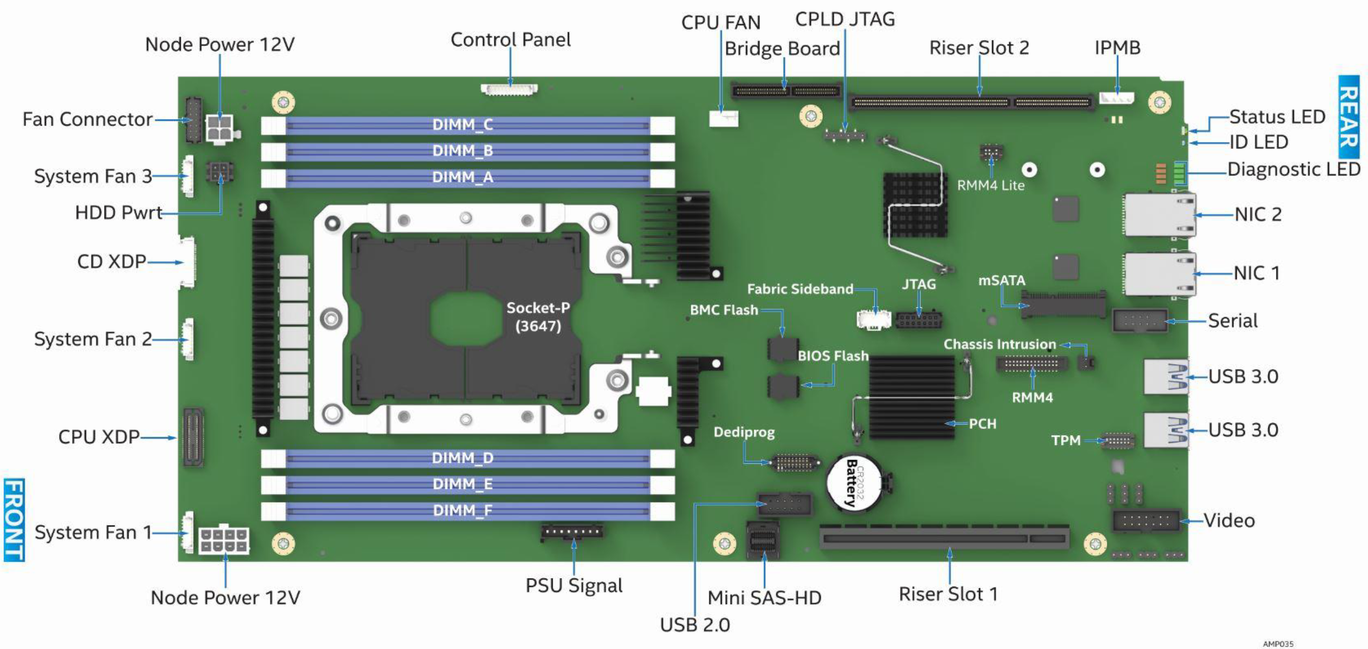
The top view of an Intel S7200AP motherboard from the manual with a bunch of named connectors
The manual contains the pinout of the connector to the bridge board. We could build an adapter to attach some buttons and an ATX power supply to it. The Node Power when the node is on can be supplied directly from the ATX PSU into the motherboard, because the 12V connectors just fit. The pinout is thankfully the same as on a normal ATX board, but even if not, an adapter cable is crimped pretty quickly and only one DigiKey order away.
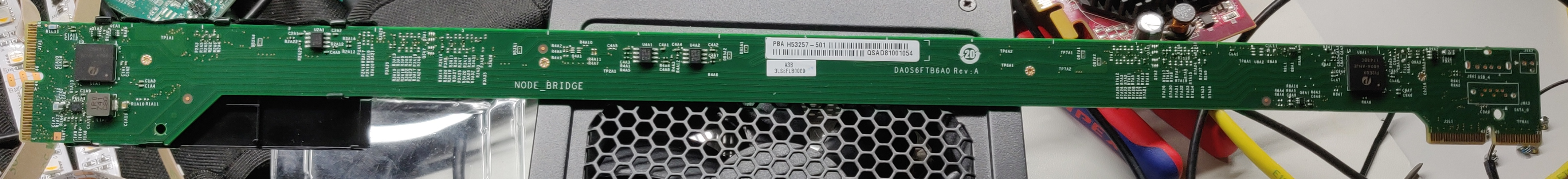
The long boiBridge Board
But wait, that pinout in the manual is the wrong side of the bridge board. It's what plugs into the motherboard, I need the other side. Thankfully, there is also a Technical Product Specification for the H2000 Server Chassis which lists its pinout to the bridge board on Page 44f. Phew, no need to reverse engineer the bridge board.
But then I glanced over the board again and found the PSU Signal and Control Panel connectors that are unconnected on my node. What do they do? The TPS for the S7200AP doesn't mention them. No pinouts, nothing.
So I tried to be smart. When reverse engineering stuff, I learned that looking left and right helps sometimes even if docs, code or specs are not a 100% fit, oftentimes they are similar and looking at them anyway and thinking about stuff might just lead you to the right train of thought to figure something out. Or it just fits because things aren't invented twice for a change. The H2000 chassis supports more nodes than just the HNS7200AP(R): For example the HNS2600TP for which I found the Technical Product Specifications.
Here the connector we are looking for is present as well, even though at a different place on the board and with a different name: Backup Power Control. When searching for this in the PDF, we get a description for what it is, the pinout and even what kind of connector I need to buy. It is exactly what we need! Power control, when the board is used in a 3rd party chassis. Which in this case is my desk. What's the pinout?
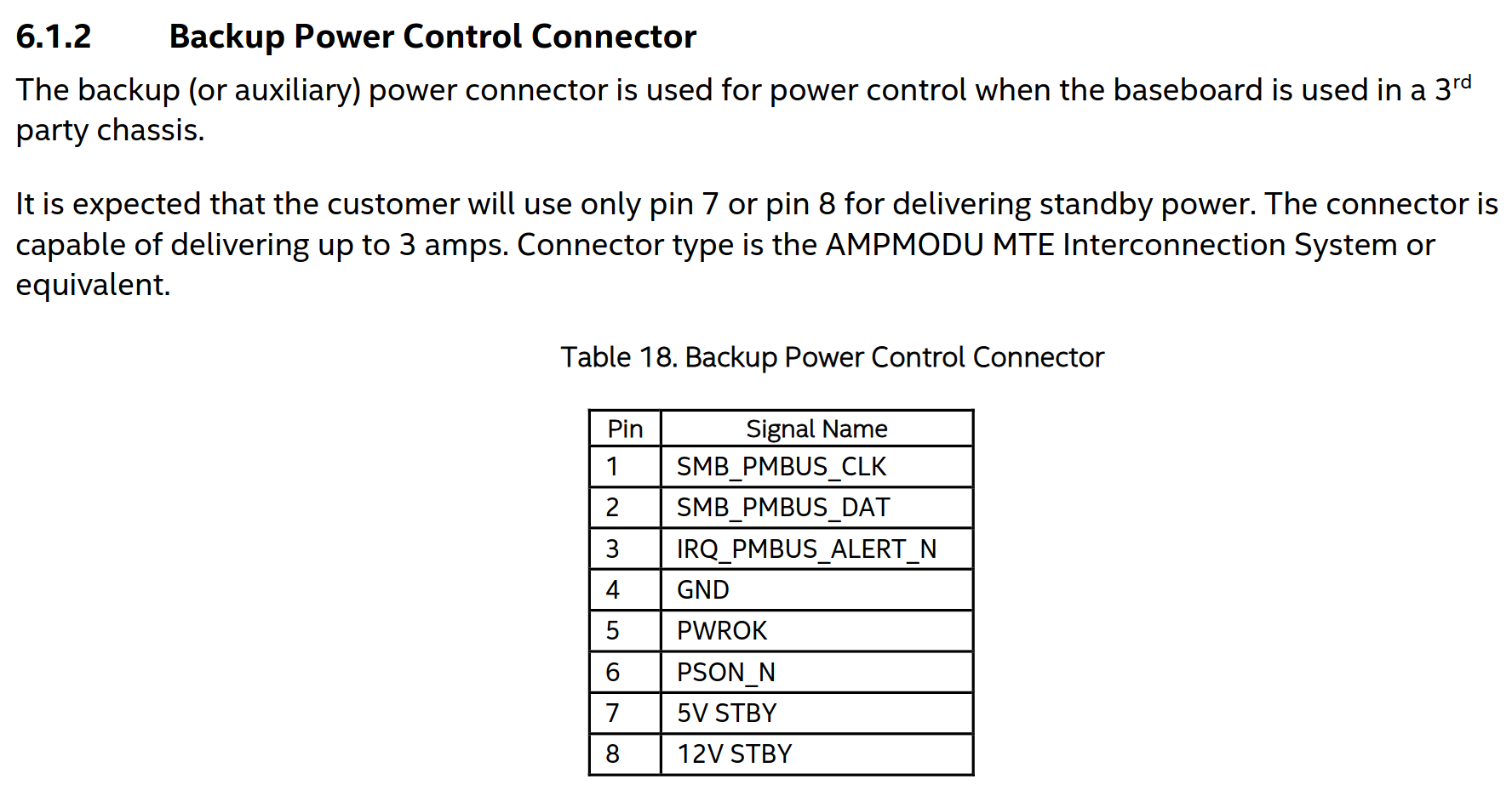
The PSU Signal connector pinout
If you ever looked at the pinout of the 20/24-Pin ATX connector, you know the names of a few of these pins:
- GND - obvious
- 5V STBY - 5V standby power that is always present as long as the PSU is powered
- PSON_N - Pulling this line low turns the main power rails of the ATX PSU on
- PWROK - when all rails are stable after power on, the PSU asserts this signal
Also the docs say that only 5V STBY OR 12V STBY need to be supplied with power. A quick check with a multimeter yielded that GND on my board is where it's supposed to be, so the pinout seems to be somewhat correct even if it's from the documentation of a different motherboard. Nice. We can build an adapter with four wires from an ATX 20/24 pin connector to this AMPMODU MTE connector, wire it up properly and use a plain ATX power supply. The beefier 12V rails fit anyway, and we can just plug them in.
Thanks, Intel! No need for a complicated adapter for the bridge board. Yes, I drew one anyway, but just the schematics so far, also a few things are guessed because I don't have the electrical specifications of the pins.
Okay, we get power to the node, how do we turn it on? IPMI over the BMC? Shit. Doesn't work! That's what we are trying to fix. Do we still need that bridge board connector breakout board? No, there is another connector labelled Control Panel. Here the HNS2600TP manual also helps us out. One page further we find this:
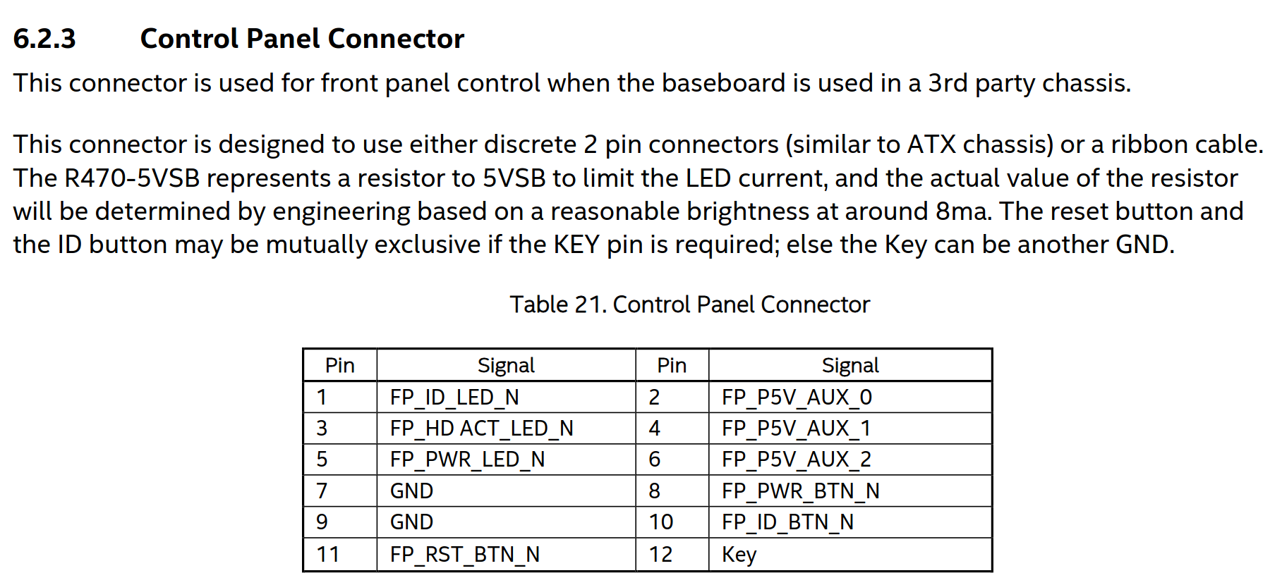
The Control Panel pinout
This again looks like a standard ATX front panel thing. Shorting the button line to GND next to the actual button line -> assert the button. The LEDs are nice to have, but we don't really care. The documentation doesn't say what connector this is, but a blind person with a bit of electronics experience can look at it and recognize that it's a 12 Pin Molex 1.25mm Picoblade connector. DigiKey also offers pre-crimped terminals, so no cursing and messing up miniscule crimps because you don't have the right 500€ proprietary crimping tool.
So, cool. We figured it out! I crimped a bunch of cables, hooked up an ATX power supply and off we go!
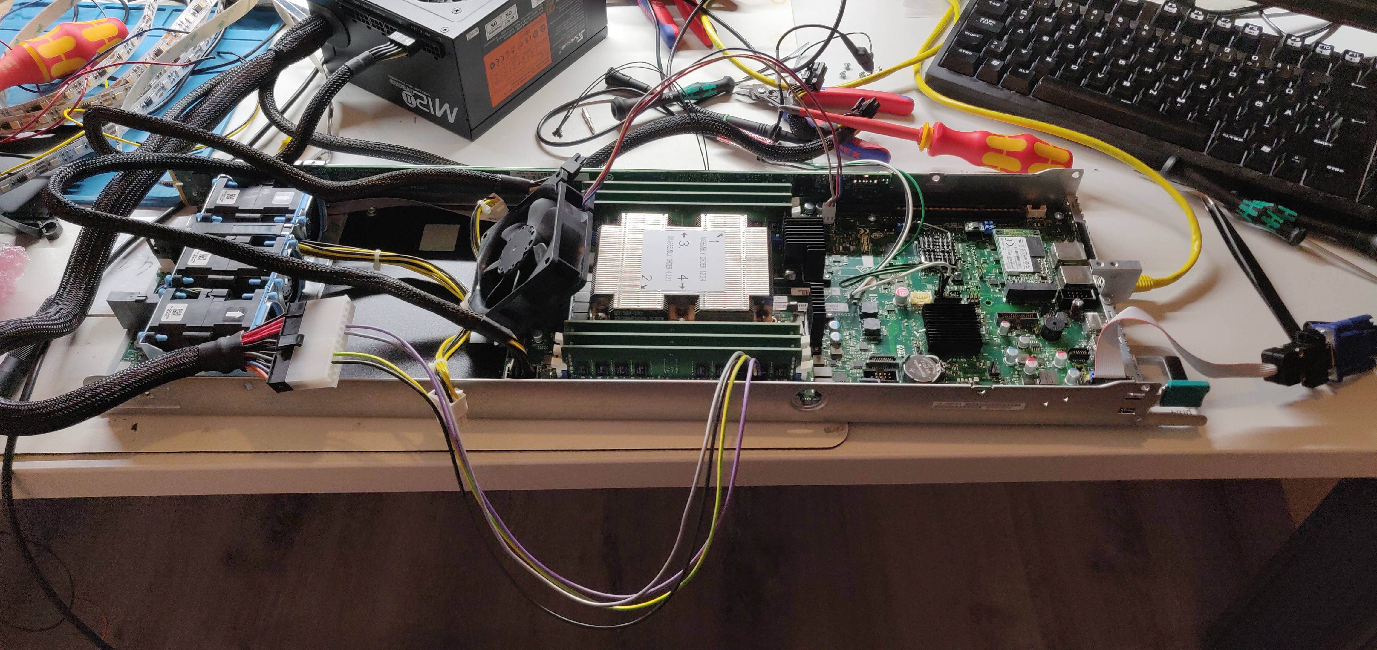
The HNS7200AP node sitting on my messy electronics desk, wired up to a regular ATX power supply by using custom crimped adapter cables and even a small push button soldered to the front panel connector to turn it on. There is also a custom 14 Pin 2.54mm IDC to VGA adapter cable plugged in which I built to get a VGA image out of the thing.
Powering the node like this bypasses the front power board which also supplies the fans with 12V. That's why I propped up this ebm Papst fan and just plugged it into the CPU fan connector on the motherboard. Not the ideal cooling solution, but it keeps the temperatures at bay when idling which is good enough for testing. Since the protective plastic cover that also double serves as an air duct is missing, the airflow is suboptimal anyway, so blowing a bunch of air over the motherboard can't hurt.
🔗The issue
Holy shit, that was a lot of foreplay. Andy, get to the point! Why are we even doing all this?
Yes, we'll get to that now.
So the node boots into the operating system, it gets an ethernet link once it booted up, it acquires a DHCP lease and Ethernet generally works, so the i210 works and the cables are also okay. But even once the i210 has been initialized by an OS, the BMC didn't receive a DHCP lease. Also switching from the first to the second interface didn't yield any change. Turning the system off and on again didn't change anything either.
The first thing I did, after turning it off and on again, was just reset all settings. I went into the UEFI and reset everything to defaults. No change, that would've been too easy.
Then I attempted to just reflash the UEFI and BMC firmware. I prepared a USB stick, booted into the UEFI shell, ran the update script, and it complained that the UEFI image is corrupt or whatever, but reflashed the BMC. I didn't think a lot about this at the time. Later I found a topic in the Intel support forums by somebody else which explained that the currently running UEFI really seems to have gotten corrupted and that the update is rejected because of this. To solve this, you can boot into a backup UEFI and run the update from there. This reflashes the regular UEFI and queues an update on next boot for the backup BIOS. I performed all of this, and I could update the UEFI again. That however didn't solve any of my other problems. It's still weird that this happened though.
When I ran ipmitool on Linux to show the currently configured network settings on the BMC, I got this:
[andy@phi4 ~]$ sudo ipmitool lan print
Set in Progress         : Set Complete
Auth Type Support       : MD5 PASSWORD
Auth Type Enable        : Callback : MD5 PASSWORD
                        : User     : MD5 PASSWORD
                        : Operator : MD5 PASSWORD
                        : Admin    : MD5 PASSWORD
                        : OEM      :
IP Address Source       : DHCP Address
IP Address              : 0.0.0.0
Subnet Mask             : 255.255.255.0
MAC Address             : 00:00:00:00:00:00
SNMP Community String   : public
IP Header               : TTL=0x00 Flags=0x00 Precedence=0x00 TOS=0x00
BMC ARP Control         : ARP Responses Enabled, Gratuitous ARP Disabled
Gratituous ARP Intrvl   : 0.0 seconds
Default Gateway IP      : 0.0.0.0
Default Gateway MAC     : 00:00:00:00:00:00
Backup Gateway IP       : 0.0.0.0
Backup Gateway MAC      : 00:00:00:00:00:00
802.1q VLAN ID          : Disabled
802.1q VLAN Priority    : 0
RMCP+ Cipher Suites     : 0,1,2,3,4,6,7,8,9,11,12,13,15,16,17,18
Cipher Suite Priv Max   : Xaaaaaaaaaaaaaa
                        :     X=Cipher Suite Unused
                        :     c=CALLBACK
                        :     u=USER
                        :     o=OPERATOR
                        :     a=ADMIN
                        :     O=OEM
Bad Password Threshold  : 3
Invalid password disable: yes
Attempt Count Reset Int.: 30
User Lockout Interval   : 10
Notice anything? The MAC address is all zeros. That's not the case on other boards. Weird. Maybe that's the reason why networking on the BMC stopped working entirely?
The problem is, I have no insight at all into the BMC. No logs, no shells, but a socketed SPI firmware flash. So I removed it from the socket and read it out with a TL866II I had sitting on the shelf. Newer motherboards don't have the firmware SPI flashes socketed anymore, so I think this one is a pretty early revision. It also has all kinds of debug connectors populated like Intel's XDP in-system debug port.
Anyway, I dumped the image, threw binwalk onto it and got a bunch of file systems out. Whoever built that IPMI format created a custom image format with signed partitions. binwalk managed to extract something, but I needed to make sense of the filesystems first.
The root file system is a squashfs packed into a uImage and is loaded as a ramdisk by uboot in conjunction with the kernel when booting. The kernel has a driver for this MTD partitioning format, apparently called ISI (which I guess stands for "Intel Signed Image" because the magic strings *SignedImage* is present multiple times in the flash image) and mounts two additional partitions:
/dev/mtdblock1 on /usr/local/www type cramfs (ro,relatime)/dev/mtdblock2 on /conf type jffs2 (rw,relatime)
The cramfs is the webroot and a bunch of other stuff. For now that's uninteresting to us, but the /conf mountpoint is interesting. It's pretty much the only writable filesystem that persists across reboots. The root fs is a ramdisk and cramfs filesystems are per definition read only. So if I want to get access to anything, exploit anything or do whatever to gain more insight, I need to mess with this.
After extracting it, I found the usual messages logfile and scrolled through it and found log lines that didn't exactly look good:
Jan  1 00:00:47 defaulthost: [174 CRITICAL][nwcfg/nwcfg.c:666]Bzzt. No good: -1
Jan  1 00:00:47 defaulthost: [174 CRITICAL][hostname.c:111]SetDefaultHostName: nwGetMACAddr() failed. Error: -1
Jan  1 00:00:47 defaulthost: [174 CRITICAL][defaulthost.c:32]SetDefaultHostName() failed in hostname process.
Where is the function nwGetMACAddr? I need to see what it does.
$ grep -r nwGetMACAddr .
grep: ./usr/local/bin/defaulthost: binary file matches
grep: ./usr/local/lib/libami.so.1.0: binary file matches
There it is. defaulthost is just the utility that errors out and calls into a shared library, so I loaded libami.so.1.0 into Ghidra and checked out what it does and why it fails.
undefined4 nwGetMACAddr(char *param_1)

{
  int __fd;
  int iVar1;
  undefined4 uVar2;
  int *piVar3;
  char *pcVar4;
  uint local_7c;
  undefined2 local_78;
  char acStack_74 [18];
  undefined auStack_62 [14];
  undefined4 local_54;
  undefined4 local_50;
  undefined4 local_4c;
  undefined4 local_48;
  undefined4 local_44;
  undefined4 local_40;
  undefined4 local_3c;
  undefined4 local_38;
  undefined4 local_34;
  undefined4 local_30;
  undefined4 local_2c;
  undefined4 local_28;
  undefined local_24;

  __fd = socket(2,2,0);
  if (__fd < 0) {
    piVar3 = __errno_location();
    pcVar4 = strerror(*piVar3);
    IDBG_LINUXAPP_DbgOut(0x82,"[%s:%d]can\'t open socket: %s\n","nwcfg/nwcfg.c",0x28e,pcVar4);
    uVar2 = 0xffffffff;
  }
  else {
    local_7c = 0;
    local_78 = 0;
    local_54 = 0;
    local_50 = 0;
    local_4c = 0;
    local_48 = 0;
    local_44 = 0;
    local_40 = 0;
    local_3c = 0;
    local_38 = 0;
    local_34 = 0;
    local_30 = 0;
    local_2c = 0;
    local_28 = 0;
    local_24 = 0;
    snprintf((char *)&local_54,0x31,"%s%d",Eth_NetWork_If,0);
    strncpy(acStack_74,(char *)&local_54,0x10);
    iVar1 = ioctl(__fd,0x8927,acStack_74);
    if (iVar1 < 0) {
      close(__fd);
      IDBG_LINUXAPP_DbgOut(0x82,"[%s:%d]Bzzt. No good: %d\n","nwcfg/nwcfg.c",0x29a,iVar1);
      uVar2 = 0xffffffff;
    }
    else {
      memcpy(&local_7c,auStack_62,6);
      close(__fd);
      sprintf(param_1,"%02X%02X%02X%02X%02X%02X",local_7c & 0xff,local_7c >> 8 & 0xff,
              local_7c >> 0x10 & 0xff,local_7c >> 0x18,(uint)(byte)local_78,(uint)local_78._1_1_);
      uVar2 = 0;
    }
  }
  return uVar2;
}
It's ugly decompiled code which I didn't clean up, but here is the gist of what it does:
- create some socket, I am too lazy to look up the type
- error out if that fails. We don't see this message, so that syscall worked out
- execute an
ioctlwith request0x8927and a pointer to something that contains the name of the network interface - if the ioctl fails, print that "Bzzt." error message. We see this, so this is what fails
- In case the
ioctlwas a success, grab the returned MAC and turn it into a string usingsprintf
Google tells us that the ioctl request is a SIOCGIFHWADDR which, surprise, retrieves the MAC address of an interface. How can this fail? Only when the interface isn't there.
🔗Debug access to the BMC
At this point I needed more interactive access than just log files. When you look at the motherboard again, you can see a connector labelled with JTAG. On the silkscreen of the board itself, it is even labelled as BMC Debug. I wondered if there is more than just JTAG on there...
So I took out my oscilloscope, hooked up ground somewhere and probed around while continuously turning the system on and off until I saw things wiggle around in the hopes that I would see the bootloader or Linux kernel printing boot messages somewhere. Turns out, there IS a debug UART on there over which I could get at least boot logs, if not a complete shell.
First I found GND by using a multimeter and just beeping out GND against a known ground point like a screw. Then TX was obvious because it wiggled around on my scope. I hooked up an FTDI and skipped the RX line for now and saw a boot log that ended in the line we all want to see:
AMI001E67FA0947 login:
Now I needed to find the RX line of the UART. Since the idle level of a UART is usually high, we expect this unconnected pin to be high as well. This was the case for a bunch of pins, but also Pin 13. Since that is next to the TX pin, I just tried my luck and hooked up the TX line of the FTDI to it and pressed some keys. I saw characters appearing on my screen, so I found both the TX and RX lines of the UART.
This is the pinout that I found out:
     +--------+
     |1*     2|
     |3      4|
     |5      6|
     |7      8|  GND
     |9     10|  GND
 TX  |11    12|  GND
 RX  |13    14|
     +--------+
The other pins are most likely 3.3V, actual JTAG pins, maybe a chip reset somewhere. I haven't bothered figuring it out yet.
Now let's try to log in...
AMI001E67FA0947 login: root
Password:
What's the password? Let's try root...
---------------------------------------------------------------------------------------
Terminal is serial port. Dropping to Maintenance shell for debug purposes
                        Please note that this maintenance shell is only intended for use by
                        Authorized,qualified personnel for maintenance purposes.
                        If you are not a A,Q personnel, STOP.
                        You risk making the card non-functional by attempting any operations using
                        this shell.
---------------------------------------------------------------------------------------
Enter Maintenance Mode?(y/n):
lol.
Oh, I am 100% qualified!
Enter Maintenance Mode?(y/n):y
# ls /
bin      conf     etc      init     linuxrc  mnt      root     sys      usr
boot     dev      home     lib      logging  proc     sbin     tmp      var
ROFLCOPTER
I won't complain. It's all I needed and wanted. And from a security standpoint it's not even as bad as it seems: The root user is just enabled and the password is just root, because I set this up to be that way. I have another spare S7200AP motherboard that I also hooked up to power and a serial port. I couldn't log in as root at first. I then remembered that I specifically enabled the root user in the UEFI menu for the IPMI user configuration and set its password to be root. After strapping a CPU onto the spare board, booting into UEFI, enabling the root user and setting its password, the login on the UART worked on the other board as well.
So now I had two boards, a working one and the broken one, and I could diff things on my bench.
🔗Figuring out what's wrong
The first thing I did was running an ifconfig to see what is going on with the ethernet interfaces. Unfortunately, I didn't save the output and I'm too lazy to break the system again just for this, so I am trying to reconstruct the output as good as I can:
# ifconfig -a
eth1      Link encap:Ethernet  HWaddr 00:00:00:00:00:00
          UP BROADCAST RUNNING MULTICAST  MTU:1500  Metric:1
          RX packets:0 errors:0 dropped:0 overruns:0 frame:0
          TX packets:0 errors:0 dropped:0 overruns:0 carrier:0
          collisions:0 txqueuelen:0
          RX bytes:0 (0.0 B)  TX bytes:0 (0.0 B)

lo        Link encap:Local Loopback
          inet addr:127.0.0.1  Mask:255.0.0.0
          UP LOOPBACK RUNNING  MTU:16436  Metric:1
          RX packets:0 errors:0 dropped:0 overruns:0 frame:0
          TX packets:0 errors:0 dropped:0 overruns:0 carrier:0
          collisions:0 txqueuelen:0
          RX bytes:0 (0.0 B)  TX bytes:0 (0.0 B)

tulip0    Link encap:Ethernet  HWaddr 00:00:00:00:00:00
          UP BROADCAST RUNNING MULTICAST  MTU:1500  Metric:1
          RX packets:0 errors:0 dropped:0 overruns:0 frame:0
          TX packets:0 errors:0 dropped:0 overruns:0 carrier:0
          collisions:0 txqueuelen:0
          RX bytes:0 (0.0 B)  TX bytes:0 (0.0 B)
eth0 is actually gone. Where is it? Also, why are all the MAC addresses zeros? Something is very broken here.
# dmesg | grep eth0
[    0.570000] eth0: Pilot3 rev 0 at f0600000, 00:00:00:00:00:00, IRQ 1.
It's there, but then it's gone at some point.
I then proceeded to figure out where the MAC addresses are stored. The full kernel log output of the network driver is this:
[    0.550000] Linux PilotII Tulip driver version 1.1.13-NAPI (May 11, 2002)
[    0.550000]   chip is Pilot3, rev 5
[    0.560000] waiting for mac s/w reset to be  done
[    0.560000] mac s/w reset done
[    0.570000] eth0: Pilot3 rev 0 at f0600000, 00:00:00:00:00:00, IRQ 1.
[    0.580000]   chip is Pilot3, rev 5
[    0.580000] waiting for mac s/w reset to be  done
[    0.590000] mac s/w reset done
[    0.590000] eth1: Pilot3 rev 0 at f0500000, 00:00:00:00:00:00, IRQ 0.
The string Linux PilotII Tulip driver looks like a nice candidate to find source code, so I did what I always do in such cases and threw it into the GitHub search and actually found a Linux kernel source tree for the Aspeed A2600 which is a successor of the Emulex Pilot 3 which we have on our Phi motherboard.
I then browsed through the code a bit to find out where the MAC address comes from. I still have no idea :D In some places an EEPROM is parsed which contains MAC addresses, so I thought about writing a userspace program that pokes the hardware using /dev/mem to dump these EEPROMs and check them out. Especially on both boards to then compare them. So I got started with an ARM toolchain, started building a Hello-World program to see if I can actually compile and statically link stuff that runs on the BMC Linux system.
I somehow needed to get this binary through the serial port I have onto the BMC. The problem is, there is nothing in busybox on that system to encode or decode binary data that I could copy as text into a shell. No uuencode, no base64, no openssl (supports base64), nothing. And then I got an idea: I have an ethernet interface. It just has the wrong MAC address. But I am root, I can fix it at least temporary.
# ifconfig eth1 hw ether 00:01:02:03:04:05
That actually changed the address, but running dhclient still didn't acquire a lease. I also saw no packets coming out of that interface on the attached ethernet switch. It will become apparent later why.
Then I remembered seeing the tulip0 interface both as an actual ethernet interface, but also in the boot kernel log:
[   11.060000] incsi: creating mux tulip0, package count = 2
[   11.060000] device tulip0 entered promiscuous mode
[   11.060000] tulip0: Promiscuous mode enabled.
[   41.070000] incsi: Mux tulip0, Chan 00 - Channel not found
[   41.070000] incsi: Mux tulip0 discovery done
[   41.080000] incsi: destroying mux tulip0
[   41.080000] incsi: destroying packages tulip0
[   41.090000] incsi: destroyed mux tulip0
[   41.090000] incsi: error creating mux tulip0
Apparently this interface is created, or at least interacted with, by the incsi module. Whatever its purpose is... Maybe it does weird things to the actual ethernet interfaces and we should just get rid of it? YEET!
# rmmod incsi
And the rmmod just hung which caused me to hard reboot the system by flipping its power switch. Then, when it came back up, the MAC address were back! What? Why? How? The boot log now contains the addresses again:
[    0.550000] Linux PilotII Tulip driver version 1.1.13-NAPI (May 11, 2002)
[    0.550000]   chip is Pilot3, rev 5
[    0.560000] waiting for mac s/w reset to be  done
[    0.560000] mac s/w reset done
[    0.570000] eth0: Pilot3 rev 0 at f0600000, 00:1E:67:FA:09:47, IRQ 1.
[    0.580000]   chip is Pilot3, rev 5
[    0.580000] waiting for mac s/w reset to be  done
[    0.590000] mac s/w reset done
[    0.590000] eth1: Pilot3 rev 0 at f0500000, 00:1E:67:FA:09:49, IRQ 0.
But that still didn't make the issue go away. Still no connectivity. I also still have no idea where these addresses are stored. They haven't vanished again, so I didn't care. It will also forever be a mystery to me why they were gone and how changing one of them made the originals come back. If they are stored in some EEPROM and manually setting them overwrites the data in that EEPROM and by doing that maybe a broken checksum, caused by some rotten bit that got flipped by a cosmic ray, gets set correctly again, why is the original address back on the next reboot and not the new one? We'll never know, but I am open to suggestions.
🔗The sideband interface
So what is tulip0 and what does incsi do? It clearly has something to do with networking, let's try to figure out what it does!
Oh, look! An init script! (I shorted it, because it's long)
SYS_DIR=/sys
SYS_NET=$SYS_DIR/class/net

NCSI_MUXES=$SYS_DIR/class/ncsi/ncsi_muxes
NCSI_CHANNELS=$SYS_DIR/class/ncsi/ncsi_channel_count

#
# $1 = interface to rename
# $2 = new interface name
#
rename() {
    if [ ! -d "$SYS_NET/$1" ] ; then
        if [ -d "$SYS_NET/$2" ] ; then
            echo "Interface $1 doesn't exist, but $2 does. Assuming renaming already done" ;
            return 0;
        else
            echo "Interface $1 doesn't exist, can't rename to $2" ;
            return 1;
        fi ;
    fi ;
    if [ -d "$SYS_NET/$2" ] ; then
        echo "Interface name $2 already exists, not renaming $1" ;
        return 1;
    fi ;
    $IFCHNAM $1 $2 ;
}

#
# $1 = interface to create mux on
# $2 = optional package count to expect (speeds discovery)
#
createmux() {
    if [ ! -d "$SYS_NET/$1" ] ; then
        echo "Interface \"$1\" doesn't exist, can't add as NCSI mux" ;
        return 1 ;
    fi ;
    intf=$1
    if [ "$2" ] ; then
        intf="$1:$2"
    fi ;
    echo "+$intf" > $NCSI_MUXES ;
    if [ "$?" != 0 ] ; then
        echo "Error adding mux $1. Check /var/log/kernmsg for details" ;
        return 1 ;
    fi ;
    return 0 ;
}

initialize_AP () {
    # Adams Pass swapped the NIC byte lanes
    rename eth0 tulip0
    createmux tulip0 2

    NCSI_CHANNEL_USED=$SYS_DIR/class/ncsi/ncsi_channel_used
    channel_used=$(cat $NCSI_CHANNEL_USED);
    if [ $channel_used == 1 ]; then
        rename tulip0n00 eth0
        adjustmac eth0 1
        adjustmac tulip0n01 1
        vlanmode eth0 all
    elif [ $channel_used == 2 ]; then
        rename tulip0n00 eth2
        rename tulip0n20 eth0
        adjustmac eth0 2
        adjustmac eth2 2
        vlanmode eth0 all
        vlanmode eth2 all
    else
        exit 1
    fi
}

case "$1" in
    start)
        is_ki
        is_rp
        is_ap

        if [ $PLATFORM_IS_KI == 1 -o $PLATFORM_IS_RP == 1 -o $PLATFORM_IS_AP == 1 ]; then
            if [ $PLATFORM_IS_KI == 1 ]; then
                initialize_KI
            elif [ $PLATFORM_IS_RP == 1 ]; then
                initialize_RP
            else
                initialize_AP
            fi
        else
            initialize_all_others
        fi
        ;;
    stop)
        echo "stop not implemented"
        exit 1
        ;;
    *)
        echo "Usage: /etc/init.d/ncsi start"
        ;;
esac

exit $ERRORS
Okay, what does this do? We are on the Adams Pass platform, so I just kept this init function.
rename renames a network interface. So this thing renames eth0 to tulip0. Oh, that's where eth0 goes and why it's gone?
After that, createmux is called with the parameters tulip0 and 2. Whatever a mux is, but it does something with files in the sysfs that belong to the incsi kernel module. It "adds a mux". Hm.
Let's look at the dmesg output again:
[   11.060000] incsi: creating mux tulip0, package count = 2
[   11.060000] device tulip0 entered promiscuous mode
[   11.060000] tulip0: Promiscuous mode enabled.
[   41.070000] incsi: Mux tulip0, Chan 00 - Channel not found
[   41.070000] incsi: Mux tulip0 discovery done
[   41.080000] incsi: destroying mux tulip0
[   41.080000] incsi: destroying packages tulip0
[   41.090000] incsi: destroyed mux tulip0
[   41.090000] incsi: error creating mux tulip0
This stuff must be triggered by this exact init script. It says that it's creating a mux on tulip0 with an expected package count of 2. That is exactly the thing that we would expect from the createmux tulip0 2 call. Also, it seems to fail at what it's trying to do. When I cat /sys/class/ncsi/ncsi_channel_used, it gives me a 0 back. It should be at least 1 or 2. And because that isn't the case, eth0 is gone, because it's not created afterwards by the init script when it renames the tulip0n00 on this mux to eth0. The question is why.
Also, the module is named incsi, the sysfs class just ncsi. I guess the i stands for Intel? Let's google like a real reverse engineer!
NC-SI, abbreviated from network controller sideband interface... Huh! That's what we are looking for.
The NC-SI enables the connection of a baseboard management controller (BMC) to one or more network interface controllers (NICs) in a server computer system for the purpose of enabling out-of-band system management. This allows the BMC to use the network connections of the NIC ports for the management traffic, in addition to the regular host traffic.
Oh! That's how you share ethernet interfaces between the host and a BMC. There is a special interface that you can siphon traffic through without the host ever seeing it.
In the meantime, I loaded the kernel module into Ghidra and clicked through it and found functions like ncsi_do_cmd that is called from all over the place for do things like retrieving MAC addresses and do other maintenance commands like asking a thing on the other side what it is, aka retrieve some identifier.
There's also a spec for this interface. Page 24 says the following:
The following tasks are associated with Management Controller use of the NC-SI:
[...]
- Initial configuration When the NC-SI interface is first powered up, the Management Controller needs to discover and configure NC-SI devices in order to enable pass-through operation. This task includes setting parameters such as MAC addresses, configuring Layer 2 filtering, setting Channel enables, and so on.
This seems to be what incsi does when creating a new mux, but the discovery fails. Also notice how the last log message after creating the mux and starting the discovery is at time 11.060000 while the first error message shows up at time 41.070000? That's almost exactly 30 seconds. This is either a very strange coincidence or some timeout we run into. I'll go with the latter.
Wait, we have a working system as well, what does the output look like there?
[   10.370000] incsi: creating mux tulip0, package count = 2
[   10.390000] waiting for mac s/w reset to be  done
[   10.400000] device tulip0 entered promiscuous mode
[   10.410000] tulip0: Promiscuous mode enabled.
[   16.420000] incsi: Mux tulip0: discovered package id 0
[   16.420000] incsi: Mux tulip0: advertising 1 channels
[   16.430000] incsi: pkg tulip0:0 OEM supported as a Springville
[   22.440000] incsi: Mux tulip0: discovered package id 1
[   22.440000] incsi: Mux tulip0: advertising 1 channels
[   22.450000] incsi: pkg tulip0:1 OEM supported as a Springville
[   22.460000] incsi: Mux tulip0 discovery done
[   22.460000] incsi: tmppkg = c6190f60
[   22.470000] incsi: tmppkg = 0
[   22.470000] incsi: Chan 0x20 sys mac - a4:bf:01:15:4c:ae
[   22.480000] incsi: Chan 0x00 sys mac - a4:bf:01:15:4c:af
[   22.500000] incsi: created mux tulip0
[   22.500000] incsi: mux tulip0 created
Now that's different! It detects two "packages" and they are Springvilles. The first one after "just" six seconds. Springville is the codename for the Intel i210 ethernet chip as it turns out, so all of this checks out. Both, management data for discovery, setup which traffic is supposed to be redirected through the sideband interface etc. but also later the actual network traffic is carried over NC-SI. The management messages have a special ethertype set, so the PHY knows what's up. It's all in the spec if you want to know more.
So if this interface doesn't work properly, the mux driver won't find any "packages". We are onto something here. We need to figure out what's wrong and fix that!
But first, let's look at how NC-SI actually works! Judging by the signal names this interface is composed of, it's just RMII. I know this from microcontroller and FPGA development projects I did in the past where I used ethernet interfaces. The ethernet PHYs are almost always attached to FPGAs or microcontrollers via MII or RMII.
RMII stands for Reduced Media Indepentend Interface. It's using half as many data signals than MII, but at a doubled clock rate. All ethernet frames are passed to or from the PHY to the MAC and vice versa over this interface.
| Signal | Description |
|---|---|
| REF_CLK | 50 MHz clock reference for receive, transmit and control interface |
| CRS_DV | Carrier sense and receive data validity for the traffic sent from one of the NICs |
| RXD[1:0] | Receive data (from the NIC to the BMC) |
| TX_EN | Transmit enable and data validity for the traffic sent from the BMC |
| TXD[1:0] | Transmit data (from the BMC to the NIC) |
It's relatively easy: There is a main clock, two lines for data received by the ethernet interface and a valid signal it can assert when that's the case, so the BMC can sample the two received bits on the RXD line on a rising clock edge when RX_DV is asserted to receive traffic. Analogous the transmission of traffic works by putting two bits of data onto the TXD line and asserting TX_EN.
But wait! That's looks like a point-to-point thing. One receiver, one transmitter for each of the RX/TX signal pairs. We are dealing with multiple here, because we have the BMC and two i210 ethernet chips.
You can see this in the block diagram from the manual of the motherboard. The NC-SI channel goes from the BMC to both of the Springvilles:
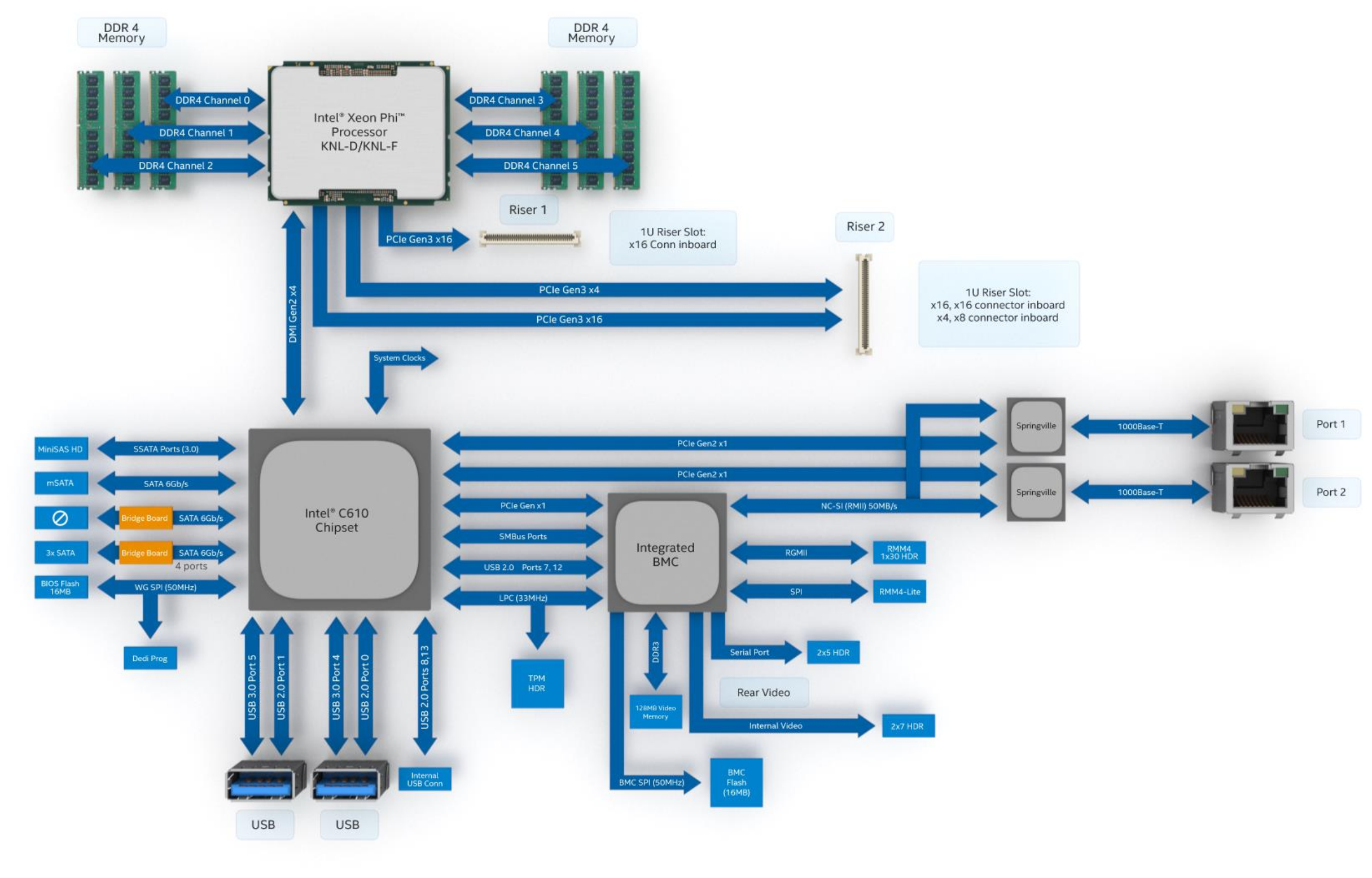
A block diagram of the S7200AP
Data coming from the BMC to the NC-SI is not a problem, both interfaces just listen and decide if it's worth to process anything further. But as soon as traffic needs to flow from the two interfaces towards the BMC, it could happen that both try to assert CRS_DV and RXD at the same time, causing a collision and possibly a short circuit. To solve that problem, there is something called an "arbitration state machine" which is a hardware feature that makes the network interfaces play nice with each other and arbitrate so that every interface gets its turn to transmit data from itself to the BMC on the RMII interface without any collisions.
The spec says:
7.2 Hardware arbitration
To prevent two or more NC-SI packages from transmitting at the same time, a hardware-based arbitration scheme was devised to allow only one Network Controller package to drive the RX lines of the shared interface at any given time. This scheme uses a mechanism of passing messages (op-codes) between Network Controller packages to coordinate when a controller is allowed to transmit through the NC-SI interface.
furthermore:
Hardware-based arbitration requires two additional pins (ARB_IN and ARB_OUT) on the Network Controller. The ARB_OUT pin of one package is connected to the ARB_IN pin of the next package to form a ring configuration [...]
The whole thing is pretty crazy. The state machine passes around a token to signify who is allowed to transmit right now. It all happens automatically and is pretty involved. The spec again goes into more detail how all of this works, what the transmitted opcodes do and how they are encoded and what the state machine transitions look like.
🔗Fixing the issue
Now, what's wrong? The communication between the BMC and the Springvilles must be somehow severed. The interfaces themselves work fine, it must be just the sideband interface.
So I grabbed the datasheet for the i210, checked the pinout and started probing around with my scope.
First just the clock line. Fine. 50MHz, just as we expected. The interfaces work, so no surprise here. Then reset lines. All deasserted. Also pretty obvious. I didn't even bother to check the supply voltage, because why?
Then I looked at the NC-SI pins. There was traffic, so it's not a physical problem where some resistor or solder joint went bad. At least I wasn't able to see that by quickly looking at the signals. I prepared myself mentally already to hook up a logic analyzer to these pins and write a decoding module to see the actual traffic over that interface to figure out what might be wrong.
While scrolling through the i210 datasheet, I saw that they can interface with SPI config flashes. They contain MAC addresses, general configuration bits for hardware registers, firmware for network booting and other stuff. Maybe I should read them out and diff them between a working and non-working board? Maybe something got corrupted?
The flashes are soldered down to the board and I would like to avoid putting a lot of heat into a rare Xeon Phi multilayer board to get them off and read them externally, so I needed to figure out how to read them using the ethernet controllers itself. Googling yielded i210-tools. After cloning the repo and fixing two build errors by adding the right includes for missing header files, I was able to read the flashes of the two ethernet chips:
$ echo "0000:03:00.0" | sudo tee ls /sys/bus/pci/drivers/igb/unbind
$ sudo ../build/i210-flash/i210-flash --dump --bdf 03:00.0 > first_i210.bin
$ echo "0000:03:00.0" | sudo tee ls /sys/bus/pci/drivers/igb/bind

$ echo "0000:04:00.0" | sudo tee ls /sys/bus/pci/drivers/igb/unbind
$ sudo ../build/i210-flash/i210-flash --dump --bdf 04:00.0 > second_i210.bin
$ echo "0000:04:00.0" | sudo tee ls /sys/bus/pci/drivers/igb/bind
The reason why I need to unbind the PCI device from the network driver is, that the kernel prevents accessing the devices by using /dev/mem when there are drivers bound to them. i210-flash does exactly that, so we need to make the kernel happy. Alternatively, you can boot Linux with the iomem=relaxed boot argument which relaxes this requirement and it works without unbinding the drivers.
I later learned that flashrom supports reading and writing the EEPROM as well, however only the first 4KiB, because it reports that the Flash is in Secure Mode. Whatever that means.
I did the same on a working board. First on my spare motherboard from my shelf, later on phi3 in the datacenter, because the differences between the spare board and phi4 were huge. The spare board is much newer and has newer firmware in the flash or whatever. I wanted to go slow and look at as few differences as possible at once.
Now let's diff that stuff!
$ binwalk -Wi eeproms_broken_phi4/first_i210.bin eeproms_working_phi3/first_i210.bin

OFFSET      eeproms_broken_phi4/first_i210.bin                                   eeproms_working_phi3/first_i210.bin
--------------------------------------------------------------------------------
0x00000000  00 1E 67 FA 09 45 20 0D FF FF 20 30 FF FF FF FF |..g..E.....0....| \ 00 1E 67 FA 0E 9F 20 0D FF FF 20 30 FF FF FF FF |..g........0....|
*
0x00000040  0C 20 84 0D 00 00 FF FF 81 02 3D 80 10 00 98 00 |..........=.....| / 0C 20 84 0D 00 00 FF FF 81 06 3D 80 10 00 98 00 |..........=.....|
*
0x00000070  FF FF FF FF FF FF FF FF 94 00 30 04 FF FF C6 33 |..........0....3| \ FF FF FF FF FF FF FF FF 94 00 30 04 FF FF C1 D5 |..........0.....|
*
0x00001000  00 1E 67 FA 09 45 20 0D FF FF 20 30 FF FF FF FF |..g..E.....0....| / 00 1E 67 FA 0E 9F 20 0D FF FF 20 30 FF FF FF FF |..g........0....|
*
0x00001040  0C 20 84 0D 00 00 FF FF 81 02 3D 80 10 00 98 00 |..........=.....| \ 0C 20 84 0D 00 00 FF FF 81 06 3D 80 10 00 98 00 |..........=.....|
*
0x00001060  00 01 00 40 4E 15 1B 40 FF FF 00 40 FF FF 1B 01 |...@N..@...@....| / 00 01 00 40 35 15 1B 40 FF FF 00 40 FF FF 1B 01 |...@5..@...@....|
0x00001070  FF FF FF FF FF FF FF FF 94 00 30 04 FF FF C6 33 |..........0....3| \ FF FF FF FF FF FF FF FF 94 00 30 04 FF FF DA D5 |..........0.....|
*
Uhuh! That's not too many differences. Also, things seem to be repeating twice in the first 8KiB with an offset of 4KiB (0x1000).
Let's dissect this using the datasheet! On page 69 (nice!) you can see an address map of the flash's different sections:

The address map of the i210 config EEPROM
The first 8KiB are two "Legacy EEPROM" banks that are used alternatively when updating firmware. The firmware update mechanism requires a double image policy to protect against power outages and apparently the legacy EEPROM is part of that, so let's look at the first 4KiB first and ignore the rest.
The first difference is in bytes 4 and 5. This one is easy: It's the different MAC addresses of the interfaces.
The third difference at offset 0x7E is also easy: It's a checksum over the first 0x7E bytes and because of that it needs to be different, because the MAC address itself is different.
What about the second difference at offset 0x49? The EEPROM is addressed in 2 byte long words, so the word address of the byte offset 0x49 is actually 0x24 and the difference is in the uppermost byte of this word, because it's stored in little endian. What is at 0x24? The Initialization Control 3 (Word 0x24) (page 195).
The word value in the broken EEPROM is 0x0281 and in the working EEPROM 0x0681, so there is a single bit that differs: Bit 10 (counting from 0).
Bit 10 is called APM Enable and here is what the datasheet has to say about this:
Initial value of Advanced Power Management Wake Up Enable bit in the Wake Up Control (WUC.APME) register.
What the fuck? APM? The 90s called, they want their power management standard back!
Let's google for i210 nc-si apm enable! On the first result page, I found a link to a document called Intel ® Ethernet Controller I210 Specification Update. That looks interesting. What does it have to say about NC-SI in conjunction with APM Enable bit?
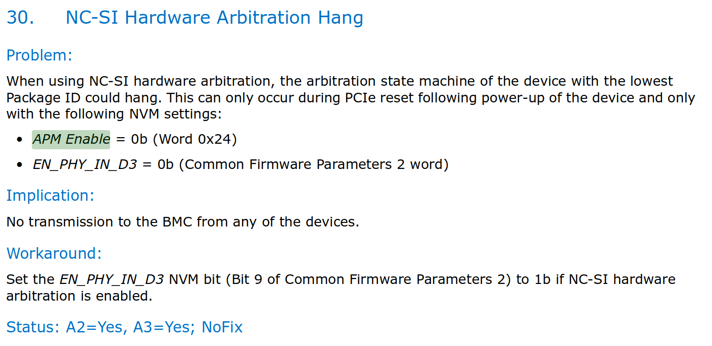
The errata about the NC-SI arbitration state machine hang when the APM Enable is cleared
No fucking way! The arbitration state machine on the first package may hang in case the APM Enable and another EN_PHY_IN_D3 bit is cleared? That would explain what we are seeing. If the state machine hangs, none of the ethernet interfaces will be able to send data to the BMC, so the incsi module can't properly talk to them and the enumeration fails. That is EXACTLY what we are seeing.
But slow! Let's not get too hyped. What is the other bit that would affect this set to?
The EN_PHY_IN_D3 bit is stored in the Common Firmware Parameters 2 word (i210 datasheet page 204) which in turn is stored in a block called the Common Firmware Parameters (i210 datasheet page 203). How do we find these parameters? They are pointed at by a pointer stored in the Firmware Module Header at word offset 0x03 (i210 datasheet page 202). How do we find the firmware module? You guessed it, via a pointer. It's stored in the Legacy EEPROM at word address 0x51. Phew...
I'll spare you the way through all these pointers. If I follow that chain of pointers using a hex editor and end up at the Common Firmware Parameters 2 word, I can see that it has a value of 0xfdc3. Bit 9 is the mentioned EN_PHY_IN_D3 bit and... drumroll it's cleared.
That's it. Both of these bits are cleared. This HAS to be the issue we are having. Now the question is what do we do? If we set one of the two bits, which one? I decided to set the APM Enable bit, just because the other Phis (the spare board as well btw) do this as well and on these boards everything works.
So let's flip the bit using a hex editor, whip up a quick python script to calculate the checksum that I just changed using a hex editor again.
#!/usr/bin/env python3

import sys

f = open(sys.argv[1], "rb").read()[0:0x80]
f = [int.from_bytes(f[i:i+2], "little") for i in range(0, len(f), 2)]

chksum = 0

for b in f[:-1]:
    chksum += b
    chksum &= 0xffff

print(hex((0xbaba - chksum) & 0xffff))
Then I took the first four KiB of the modified EEPROM, because that's all anyway we can write using flashrom and wrote it to the two interfaces:
$ sudo ./flashrom -VVVV -pnicintel_eeprom:pci=0000:03:00.0 -w /home/andy/fix/first_i210_4k.bin
$ sudo ./flashrom -VVVV -pnicintel_eeprom:pci=0000:04:00.0 -w /home/andy/fix/second_i210_4k.bin
I powered down the server, flipped the switch on the PSU to off, to trigger a cold hard reboot of everything, flipped it back on, let the BMC boot and... it works. Everything. The incsi module enumerates the packages, the mux is initialized, a DHCP lease is acquired. It's repaired. Fuck me!
🔗Outro
There are A LOT of unanswered questions here. Why was that APM Enable bit set on all other servers except on phi4? Was it ever set? Did it become unset? If so, why was the checksum that covers it still correct? How did the server forget its MAC addresses and how did I restore them by trying random stuff on the shell? Is the server fixed for real? I would guess that I rebooted the BMC over 20 times now and every time EXCEPT ONCE it worked. That one time it didn't gives me a bad feeling, but maybe it is just that flaky? How often do you reboot a BMC that something like this would even be discovered during testing?
If that bit was actually never set, how did this thing ever work? Your guess is as good as mine. I have absolutely no idea.
Interestingly, I don't seem to be the only one with this problem. Here is a forum post on the Intel forum with the EXACT SAME ISSUE on the EXACT SAME MOTHERBOARD. Unfortunately OP never posted a follow-up if that suggested BIOS update helped or not, but I already know the answer to that.
I have to admit that hunting this bug was actually fun, but at the same time, I think I fixed it by pure luck. There was enough documentation available and had I not have access to working hardware to diff the EEPROMs and the well documented erratas by Intel, this would've been an impossible path. So, thanks Intel for not being a dick this time and actually publishing documentation for your products! It helps your users, you should do that more often.
And I will definitely look up errata sheets more often in the future if I run into any kind of problem.